Bachelor thesis: Inductance based stiffness sensing catheter
For my bachelor thesis, I worked on a prototype of a stiffness sensing catheter, where I did everything from the initial simulations of the sensor, to the fabrication of the final prototype and the validation of the simulated and designed properties. The final prototype is displayed below on the right side, and the rendering (without the spring), making the insides a bit more visible on the left:

The final sensor exhibits quasi-linear properties over a measurement range of approximately 0 N to 0.2 N respectively 2.5 mm of travel with an accuracy of approximately ±5 nm if well calibrated under ontrolled conditions, and is able to distinguish different tissue stiffnesses. Some problems remained, mostly due to the high sensitivity of the sensor:
- A good displacement-configuration is necessary, as a minor change in the sensor setup can easily change the force-displacement mapping.
- The calibration had to be repeated separately for each sensor, since the production process by hand was not repeatable.
Idea
It is possible to translate the problem of finding the (local) stiffness of a material to measuring the displacement of a material when applying a specific force. Thus, we want to measure either the displacement for a known applied force, or vice versa.
Texas Instruments produces a sensor that measures the frequency at which a LCR-circuit is oscillating. This means that, if it is possible to change either the inductance, or the capacity of a part in the circuit, it will turn up in the measurements of the sensor:
\[F = \frac{1}{2\pi\sqrt{LC}}\]After some brainstorming the main ideas that emerged were the ones below:
- The first design has the advantage that a large movement range is possible by simply extending the coil and the core. However, due to the tight dimensions that the catheter is supposed to fit (the smaller the better, the goal was about 4mm diameter), it is hard to fabricate, and requires custom coils.
- The second design is a more common one, and relatively well studied. A big downside is the hard limit of the range. In addition, some simulations showed a low sensitivity, i.e. no big change in the measurement of the sensor.
- The third design would rely on the coil acting as the spring as well. The obvious downside is the limitation in material change this imposes (springs are usually not made of copper, and coils are not made from steel). Additionally, the coil/spring would be part of the circuit, meaning that there is extra danger of exposing the patient to a current.
Some initial simulations lead to the decision to focus on the first design, due to the largest sensitivity, possibility of a compact design, and likely the safest version, as the circuit is shielded by a bit more material.
Using a wound coil with a hollow core, we insert a copper core into it. This has several effects that change the inductance of the circuit. The most important are the eddy currents that are induced in the copper core, which produce a electrical field that counteracts the field generated by the coil, and thus diminishing the inductance of the coil.

Hence, the further the core is pushed into the coil, the lower the inductance becomes, and the higher the frequency of the circuit is measured. While probably possible to figure out an analytic expression for this change, we validated the design of the core/coil system using COMSOL, and then fabricated the coil ourselves. This coil was then used to study the effects of the insertion of the core in reality.
The design parameters affecting the inductance, and the change in the inductance once the core is inserted are shown on the right.
Simulations
The simulations were mostly used to decide what material to use, what frequency to operate at, and to determine raw guidelines for the design of the coil and the core.
As it turns out, there are several effects at play, that operate at very different frequencies, and are counteracting one another in between. The simulations were a way to get an initial feeling for the things that are happening, and what is desirable, respectively how to counteract the undesired effects. The two effects that are influencing the inductance of the coil when inserting the core are:
- Ferromagnetic effects: The (arguably) more commonly used effect to change the inuctance of a coil is the ferromagnetic effect, which occurs at low frequencies, where the magnetic domains in the iron core align with the external magnetic field. This effect is negliglible for copper, since it is not ferromagnetic. The effect also diminishes strongly at high frequencies due to the diminishing penetration depth of the magnetic field.
- Electromagnetic effects: At high frequencies, eddy currents are induced in the inserted core, counteracting the magnetic field from the coil, leading to a decrease in inductance.
Comparing the insertion (0mm is fully inserted, 6mm is where the bottom of the core is aligned with the top of the coil) of an iron core (Material 1) and a copper core (Material 2) at their respective ‘best’ frequencies, the effects are the following:
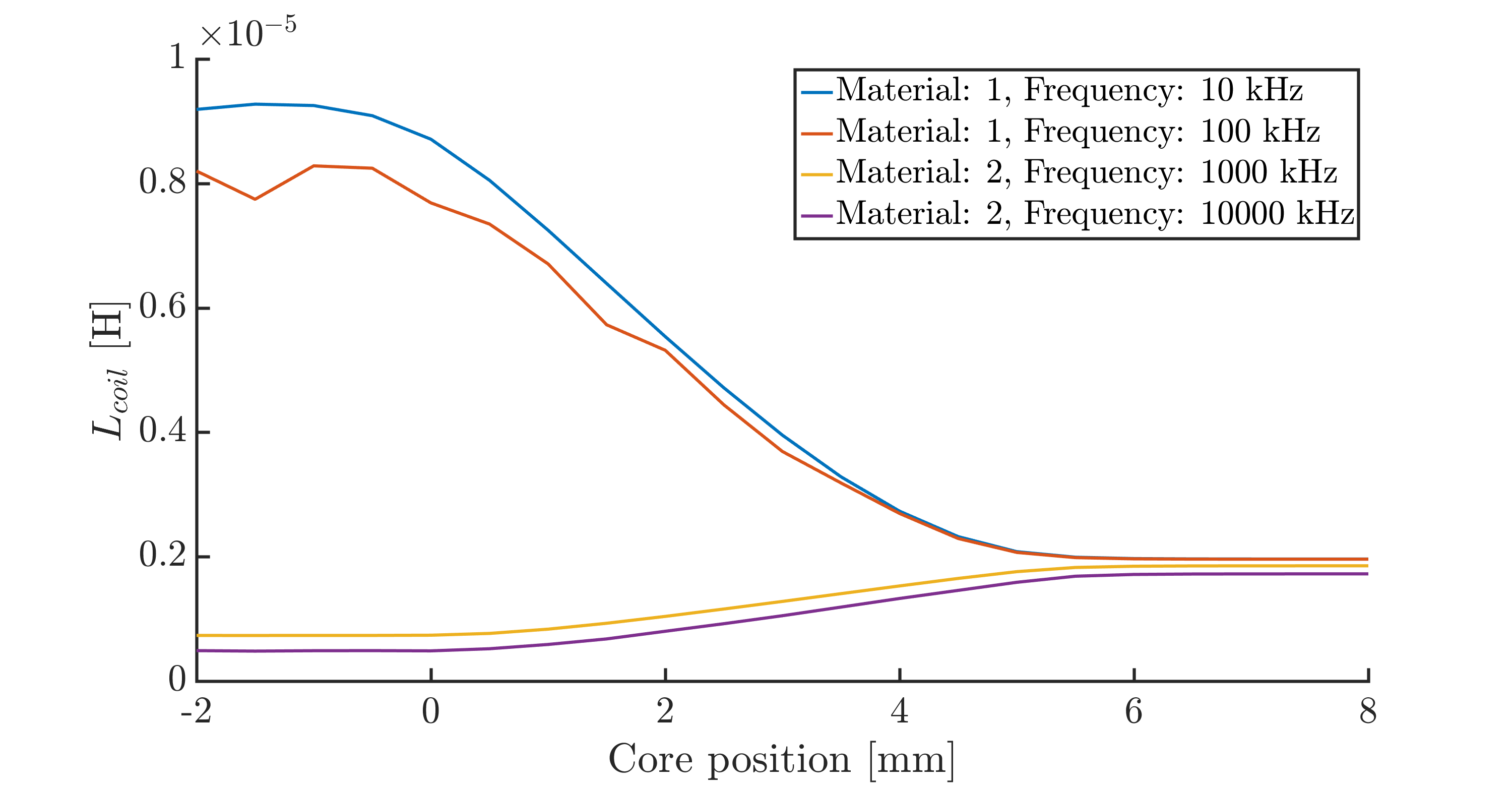
While this illustrates that the change in inductance is larger when using an iron core, the absolute change in the oscillating freuqency is higher when using a copper core, since we are operating at a much higher frequency.
The plot above also shows that the change in inductance is almost linear, for the insertion of the core for both materials, which is a very desirable property, giving a more or less equal resolution over the whole measurement space.
Manufacturing
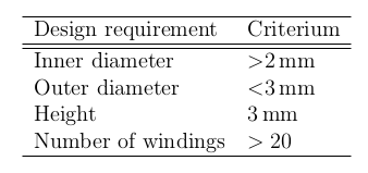
Again, due to the size requirements (the most important ones are listed on the right), it was impossible to source the micro-coils from a commercial producer. We found one company that was willing to make coild for us, but the lead time would have been too long (several weeks), and the cost too high (several thousand swiss francs) for a prototype on which we would have to iterate.
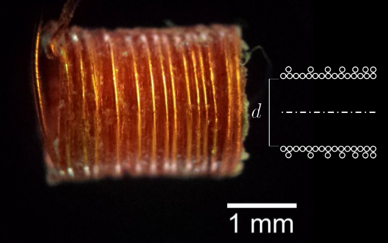
Thus, the coils were hand wound using a lathe and a teflon rod as the core, on which the copper wire was wound. We manually counted the number of revolutions, and glued the first and the last layer to avoid deformations later on. The removal from the teflon rod is easily possible due to its low friction coefficient.
Below, some (only sucessful versions) are shown:

The different colors are partly due to using different wires (to control for e.g. wire-diameter), and different settings when taking the pictures. The icons show the number of windings, and layers of the coils.
After deciding which initial coil to use, the rest of the design was relatively staightforward - the enclosure of the catheter was designed and fabricated with a high quality 3D printer, the circuit was designed, and subsequently fabricated by seeed studio, and the spring was an off the shelf spring already used for a previous project.
Optimization
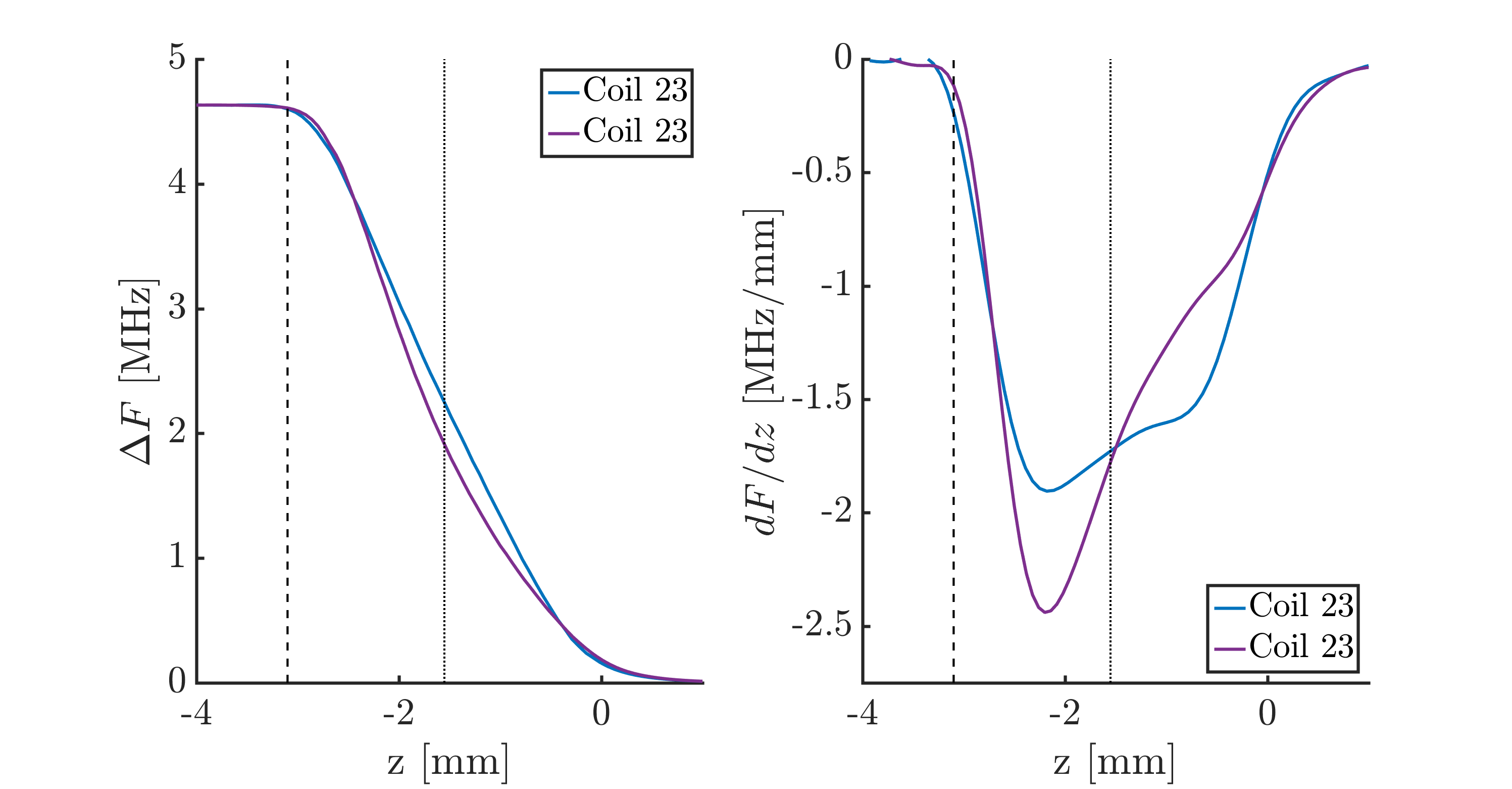
It turns out that the change in frequency of a single-layer coil is far from linear, as shown in the plot of the gradient of the frequency:
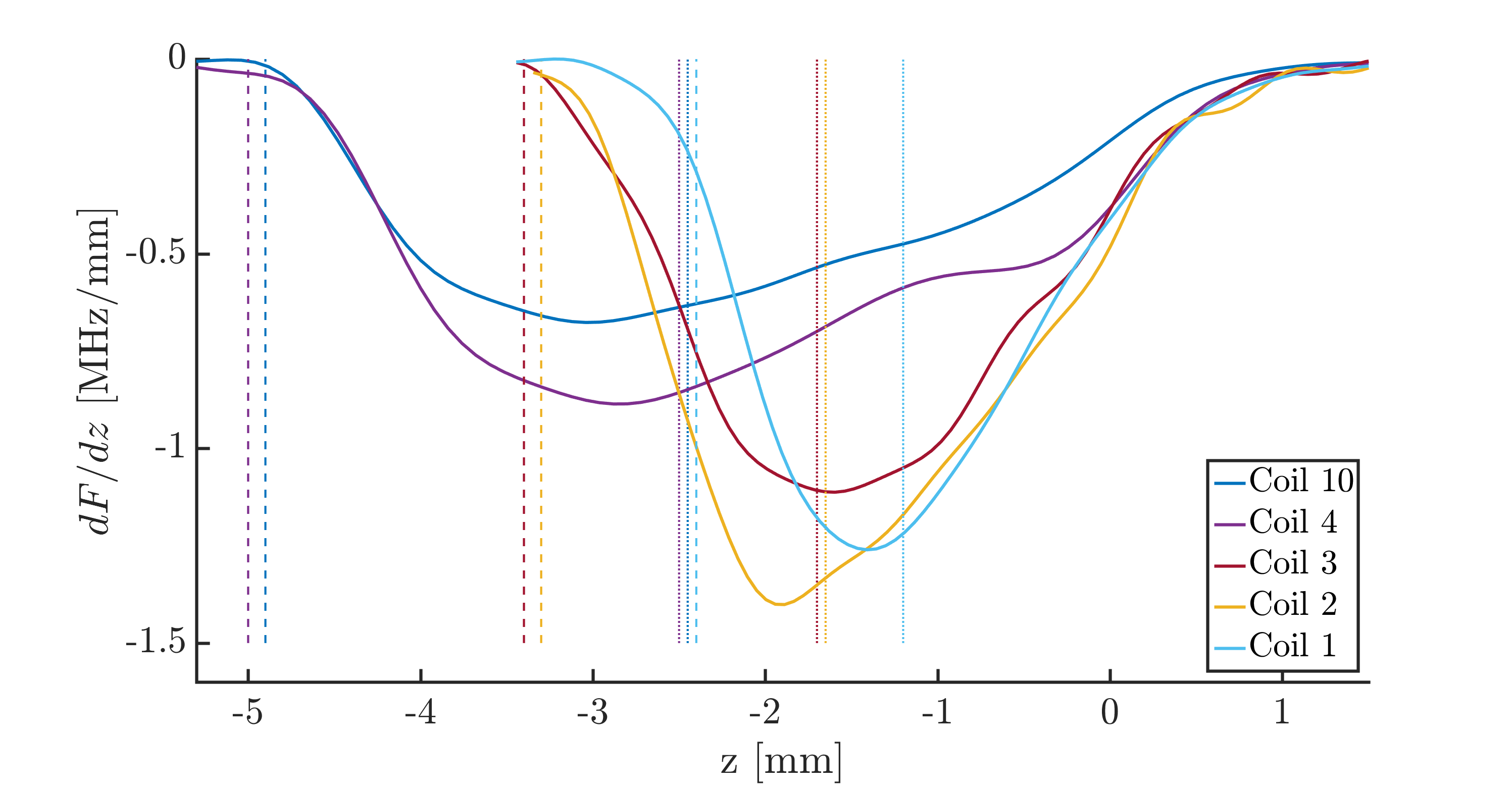
with some optimization1 of the distribution of the windings over the length of the coil, an asymmetric coil was fabricated, with ‘linearly’ decreasing density of windings. The motivation for the linearly decreasing winding density was the desire to achieve a stronger electrical field at the top of the coil, since the gradients observed in the ‘standard’ coils were low at the point of insertion.
1 What I decided to optimize for was the minimum sensitivity over the range where the catheter would be used, i.e. $$c = \max \min \left(\frac{dF}{dz}\right)$$ This is essentially trying to maximize the range over which the sensor gives a certain accuracy.
Here, the problems with the production process of the coils can once more be observed - achieving a consistent decrease in windings at this size is almost impossible by hand. Still: using this coil, the following result was achieved, where the purple line shows the usage of the coil oriented in the other direction, i.e. the direction where the weaker field is at the point where the core is first inserted.
Possible future work
- As mentioned above, the fabrication process of the coils can definitely improved upon. Moving from manual work to i.e. a simple robotic process has the potential to improve the repeatability drastically.
- First steps were already made in the direction of optimizing the coil. This can be pushed further with a comprehensive mathematical optimization process. To achieve this, a model would have to be built that mirrors the physical effects, and from there, the optimization process should be straightforward.