Robotic stippling: A naive approach
or: Abusing lab equipment
I am abusing a robot arm in our lab for things that could be done quicker by hand. I do see this partially as 'learning a bit more about real-life robotics problems', and partially as the first step towards doing the same thing I am doing here with two robots simultaneously.
Stippling is a drawing technique that only uses dots to create darker and lighter areas by varying the density of the dots. In doing so, images can be approximated - Stippling could essentially be seen as a analog version of ditheringHere is a decent overview on plotting raster images in general - stippling being one of them. .
I want to do stippling with a robot. For now, I am just going to assume that my input is a list of dots which I want to make on the paper. The goal of this post is to present a pipeline that results in those dots on a piece of paper made by a robot arm.
Particularly, I want to use the robot arm we have standing around in our lab. The robot(s) can be seen in an unrelated video below.
My goal here is not really actually getting to the end product as efficiently as possible, but rather learning a few things along the way, doing most of it myself, and later on obtaining an “optimal-ish” pathAlso see my research - I am generally interested in various forms of path planning.
.
Related work
I am obviously not the first one that has the idea of drawing dots on a paper. Pen plotters are very often used for this, and some people that sell pen plotters provide the quasi-standard for turning images into stippled images (i.e. a list of coordinates for the dots).
There’s also a lab that wrote at least one paper on stippling with an aerial robot.
I was not able to find anything on stippling with a robot arm, which is quite a bit different than using a pen plotter, or a quadcopter. With a pen plotter, the position of the dot that is being drawn easily translates into the configuration of the two-axis robot. For an arm, this is not the case anymore. This also means that the movement between points is not as straightforward as in the pen-plotter case, where we can simply drive to the next coordinates easily along the rails. But using an arm is more fun (and it is what I have available here)!
Making dots: Figuring out the path
To actually make dots on a piece of paper, we need to compute a path for the robot that makes the dots. To compute the path that the robot needs to follow, we need to know two things:
- the order in which the dots should be drawn, and
- the pose that the robot needs to be in to actually make a dot onto the paper.
We solve these in inverse order: We first compute the pose in which the robot needs to be in, and then we take these poses and figure out how to go through them to efficiently draw all of them.
Sampling positions: Solving an inverse kinematics problem
Finding a pose of the robot that results in the tip of the pen being in a certain place in 3D-space is known as inverse kinematics problem.
For simplicity, (for now) we are going to assume that there is only one robot-configuration per dot. It would be possible to allow multiple configurations that all result in the same dot, and that would make the resuling path likely shorter (because we can choose the best of all the configurations) but also much more complex.
Now, with the assumption that we only need a single valid pose for each dot, we can frame the inverse kinematics problem as optimization problem, which we can then solve using any off the shelf solver. The constraints are:
- the tip of the pen should be where the dot is supposed to be
- the robot should not collide with anything
- the angle between the pen and the surface should be roughly 90 degrees
Setting up that optimization problem in KOMO (the optimizer we use in our lab) looks like this:
1
2
3
4
5
6
7
8
9
10
11
12
13
14
15
16
17
18
19
20
21
22
23
24
25
26
27
28
29
30
31
KOMO komo;

komo.verbose = 0;

// set up komo problem
komo.setModel(C, true);
komo.setDiscreteOpt(1);

komo.world.stepSwift();

komo.add_collision(true, .001, 1e2);
komo.add_jointLimits(true, 0., 1e1);

komo.addObjective({1.}, FS_position,
    {STRING(prefix << "pen_tip")}, OT_eq, {1e2}, point);
komo.addObjective({1.}, FS_vectorZ,
    {STRING(prefix << "pen")}, OT_sos, {1e1}, {0., 0., -1.});

for(uint i=0; i<10; ++i){
  komo.run_prepare(0.0, true);
  komo.run();

  arr q = komo.getPath()[0]();

  if (komo.getReport(false).get<double>("ineq") < 1. &&
      komo.getReport(false).get<double>("eq") < 1.){
    return q;
  }
}

return {};
We can now use that function to generate a pose that deposits ink at a specified position.
Ordering points
Now that we have all configurations that we need to connect (by simply calling the function above a bunch of times), we can compute the paths between them and the order in which we want to visit the poses.
Does that sound like a traveling salesman problem? Because it is.
However, we do not really want to compute all the paths between all the poses. We hence approximate the cost to get from one pose to another one simply as the euclidean distance between the poses. This distance can be very different from the point-to-point distance, but it does represent the path length respectively the time that it takes to get from one pose to another relativly wellGenerally, it underestimates the actual pathlength, but it does so for all the paths. .
Another reasonable estimate of the pathlength/time the robot takes to get from one point to another is the L1 distance between the two poses. This can be justified by assuming that all joints move independently and our path-cost is dominated by the joint that is the slowest.
With this estimate, we could then use any algorithm that can be used for the general TSP problem. To get something up and running, I opted for a greedy one: simply taking a starting point, and then always going to the next best pose. This is known to be very suboptimal. We do attempt some local improvements after finding this greedy order, namely randomly reversing parts of the best tour, and keeping the new one if it was shorter. This improved the resulting path for the robot quite a bit in some casesI also briefly tried simulated annealing, but could not get a good solution. .
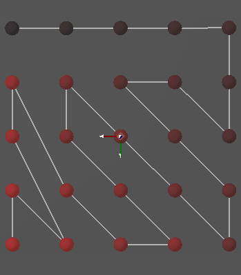
Two examples for the orders we get there (from dark to red)These do not look very optimal, but keep in mind that (1) they are not optimized to be the optimal path in euclidean 2d-space, but in the configuration space of the robot and (2) they might simply not be optimal, since the ordering algorithm we use is not optimal at all. :
Connecting the positions
To find a path between two poses, we could simply interpolate between the two. That might not be feasible, as our arm might crash into the table for example. To connect the positions, we once again formulate an optimization problem. Since we are in a very controlled environment without any massive obstacles, and we have some very specific constraints, this works well for us here, even though it might not in the general case.
Again, the constraints we have are:
- start at the starting pose with zero velocity
- end at the final pose with zero velocity
- avoid collisions
- keep a safe distance between the table and the tip of the pen
Specifying that problem in komo looks like this:
1
2
3
4
5
6
7
8
9
10
11
12
13
14
15
16
17
18
19
20
21
22
23
24
25
26
27
28
29
30
31
32
33
34
35
36
37
38
39
KOMO komo;

// set up komo problem
komo.setModel(C, true);
komo.setTiming(1, 10, 1, 2);
komo.add_qControlObjective({}, 2, 1.);

komo.world.stepSwift();

komo.add_collision(true, .001, 1e2);
komo.add_jointLimits(true, 0., 1e1);

// make pen tip go a way from the table
komo.addObjective({0.1, 0.9}, FS_distance,
    {"table", STRING(prefix << "pen_tip")}, OT_ineq, {1e1}, {-offset});
komo.addObjective({0.1, 0.9}, FS_distance,
    {"table", STRING(prefix << "pen_tip")}, OT_sos, {1e1});

// position
komo.addObjective({0}, FS_qItself, {}, OT_eq, {1e2}, q0);
komo.addObjective({1}, FS_qItself, {}, OT_eq, {1e2}, q1);

// slow at beginning and end
komo.addObjective({0.0}, FS_qItself, {}, OT_eq, {1e1}, {}, 1);
komo.addObjective({1.0}, FS_qItself, {}, OT_eq, {1e1}, {}, 1);

for(uint i=0; i<10; ++i){
  komo.run_prepare(0.);
  komo.run();

  arr path = komo.getPath();

  if (komo.getReport(false).get<double>("ineq") < 1. &&
      komo.getReport(false).get<double>("eq") < 1.){
    return path;
  }
}

return {};
Which we can then use to compute a path from pose to pose.
Simulated results
Using the logo of our lab as an example, we get this animationThe second robot needs to be there as well, otherwise it would not be taken into account for collision avoidance. :
In practice, the dots that the robot makes are likely much smaller, and thus to make a reasonable attempt at ‘replicating’ an image, the image needs either more dots, or needs to be smaller. In general, the density should be higher, otherwise the human eye just sees dots, and not the actual image.
Execution on a real system
Now for the harder part: executing this on the real system. The arms we have are from franka emika, equipped with robotiq grippers.
To be sure that we do not smash the tip of the pen into the table if the height we have the points at is slightly off, or the robot simply is not accurate enough, some form of a compliant mechanism would be good. This also makes sure that we have some play room for actually depositing ink, since we do not want to rely on being perfectly accurate, and just hitting the paper with the tip of the pen.
Ideally, the gripper should be equipped with some form of force feedback that simply tells me when the tip of the pen touched the paper. Another (mechanical) possibility would be building some form of a compliant mechanism for the pen using springs.
Since I do not want to modify the gripper too much, and building some spring-mechanism that I could put a pen into is too much effort for this project, I’ll put the piece of paper on wood, which we place on some fabric.
Moving from pose to pose
One of the primitives in our codebase to move the robot is called move and takes a discretized path as input along with either a total time, or timestamps.
This is what I am using for executing the path we previously computed.
Ideally, one would execute this in a feedback loop for better accuracy - however, we’ll first try an open loop execution without position control. This should still be good, as the model that we have of the arms’ dynamics are fairly accurate.
Executing this in an open-loop setting looks like this:
And gives these results:
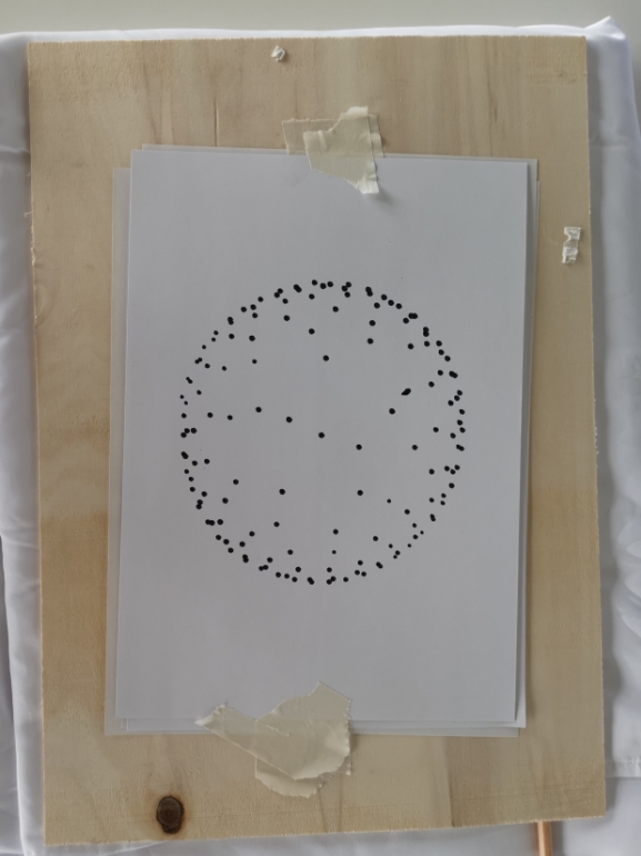
In the right image, it is visisble that the circle is a bit elongated. I am not sure if that has to do with my setup, or if that is an artifact of the open-loop execution with a bit of model error.
Takeways
My main takeway up until here is that the majority of the computation time is spent on actually finding the poses that make the dots. Approximating the solution to the TSP is fairly quick.
Executing the paths on the robot was straightforward, with a few caveats:
- The board that I put the paper on was a bit crooked. That meant that I had to downsize the images.
- Fine-adjustment of the pen-position in the gripper is a bit of a hassle.
That being said, I am pretty happy with these results.
It is visible in the videos that the robot is able to make 20 dots in 12 seconds, with quite a bit of the time being spent in transition. With that speed, that would mean that an image consisting of 1000 dots would take roughly 10 minutes to produce. However, the computation of that many points would take a long time in itself, which is likely to be the limiting factor.
So here’s some things that I might look at next:
Next (read: ideas?)
- Timeoptimal paths for an arm?
- This would require better estimation of distances between poses (i.e., the time it actually takes to get from one pose to another). It would also be benefitial to properly solve the traveling salesman problem.
- However, none of this really gets to the heart of the problem: We would need to do proper multi-goal motion planning, instead of first sampling some poses, and then optimizing the ordering in between.
- Generally, the existing literature I was able to find on multi goal motion planning assumes a single pose for each goal, and does not deal with goal regions. The only article that does was this one.
- Utilizing two robots.
- Enables color differences, or different dot sizes.
- Using both arms simultaneously is a much harder problem than just planning for one at a time. Since now the moving robot arm needs to be avoidedThis would also be a pretty cool research problem. .
- Speeding everything up
- Generating the samples is at the moment by far the slowest part of the process. This could have various reasons, but the main one isFrom previous experience in my phd, see [1], [2] the fact that using an optimizer to jointly sample positions is just not a great approach. There is research out there on that topic (speeding up repeated constrained optimization), and I am interested in that myself, so that might be a suitable next step.